Iperf Autoincrement
February 14, 2024
This is a quick start guide for setting up the Iperf Autoincrement test environment in the rXg.
For this we will need 3 rXg's. They can be physical or virtual, in this guide we will be using 3 virtual machines in ESXI. There will be a client machine that simulates the traffic (Connects to the LAN of the Router system), the router machine which is routing the traffic (this is the system we are testing against), and the last machine is the server, this represents the WAN (connects to the WAN of the Router system.)
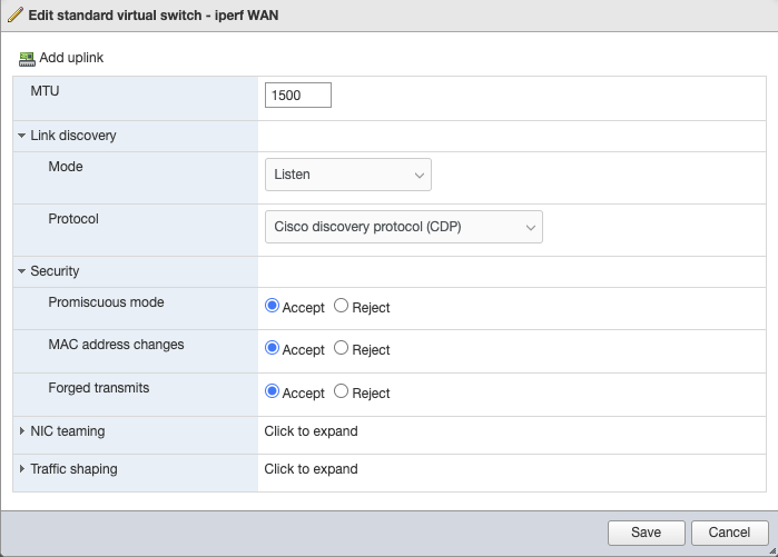
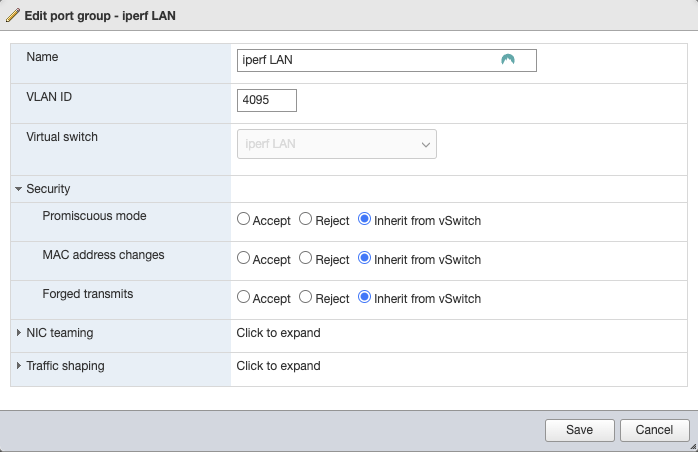
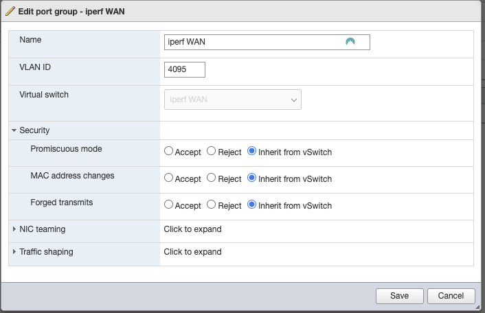
In ESXI I created a vSwitch called Iperf LAN and Iperf WAN, these do not have an uplink associated with them. Then you will need to create a port group attached to the Iperf LAN / WAN vSwitches. On the LAN port group make sure the VLAN ID is set to 4095, this will make it a trunk port.
 Screen Shot 2024-01-29 at 3.28.44 PM.png 48.25 KB
 Screen Shot 2024-01-29 at 3.30.20 PM.png 48.26 KB
 Screen Shot 2024-01-29 at 3.31.11 PM.png 45.92 KB
 Screen Shot 2024-01-29 at 3.32.17 PM.png 47.41 KB
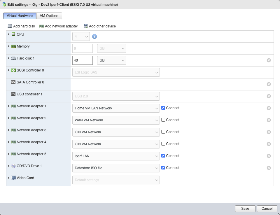
Here is the settngs for the Client VM. Network Adapter 1 is connected to the LAN network that runs my house. This gives me a way to access the system that isn't over the test network. The other adapters are disconnected, and lastly I have Network adapter 5 connected to the Iperf LAN network.
 Screen Shot 2024-01-29 at 3.35.21 PM.png 95.01 KB
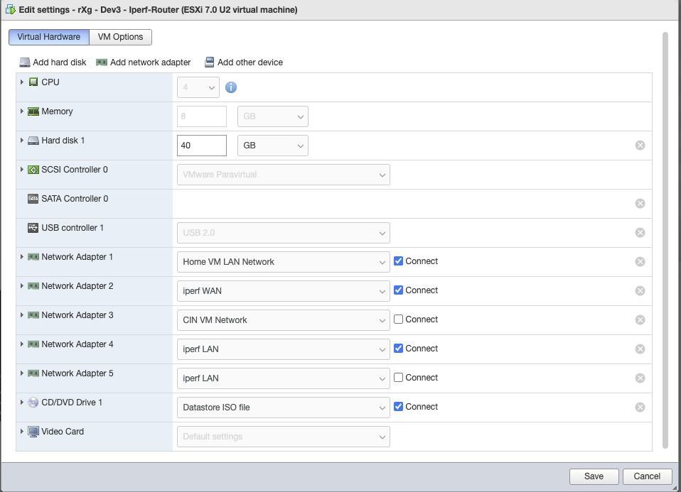
Next we have the Router VM. I have one Interface connected to the VM LAN Network, this is for my access and is not a part of the test environment. The next adapter is connected to the Iperf WAN port group, the traffic from the client machine will flow through this to the Server machine where the Iperf server is running. The last adapter is connected to the Iperf LAN port group.
 Screen Shot 2024-01-29 at 3.38.29 PM.png 93.32 KB
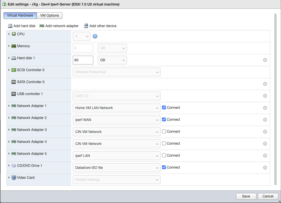
Lastly we have the Server VM. The first interface is connected to the VM LAN for access, and the next interface is connected to the Iperf WAN port group.
 Screen Shot 2024-01-29 at 3.40.09 PM.png 93.91 KB
Next we will need to SSH into each of the systems to generate the Templates that we will run on each machine. Once you in the cli navigate to /space/rxg/console/tools.
Screen Shot 2024-01-29 at 3.40.09 PM.png 93.91 KB
Next we will need to SSH into each of the systems to generate the Templates that we will run on each machine. Once you in the cli navigate to /space/rxg/console/tools.
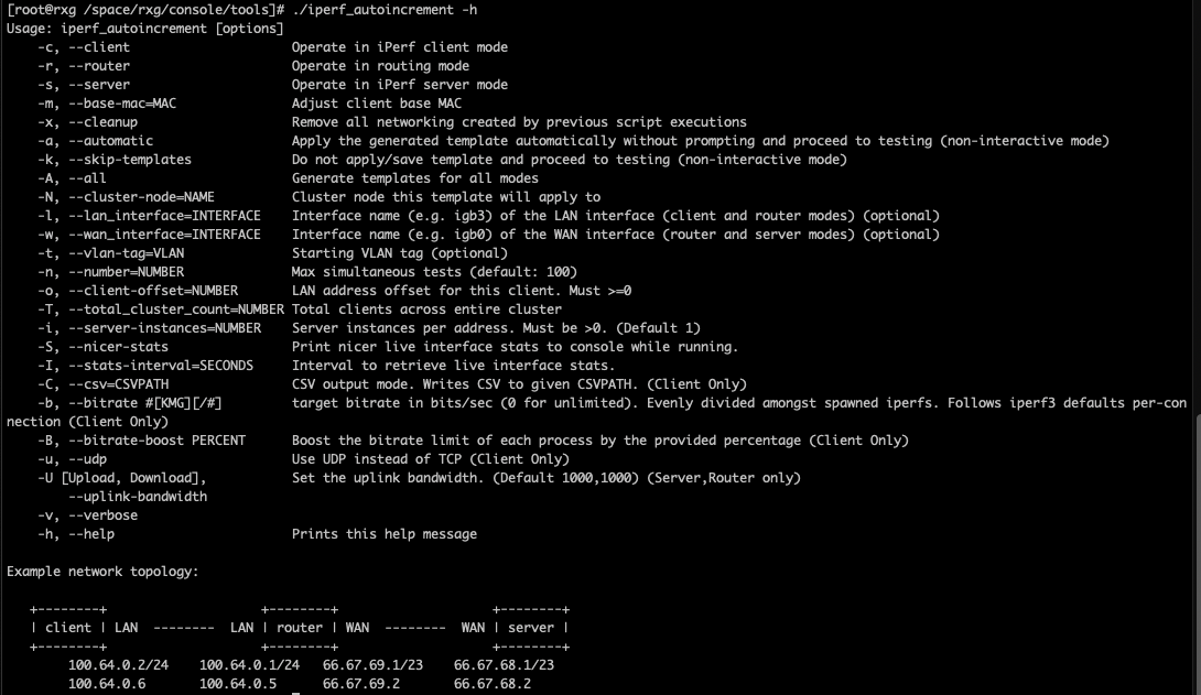
Run the following from the /space/rxg/console/tools directory: ./iperf_autoincrement -h
This will bring up the help for the script, as you can see what we have done above, resembles the diagram at the bottom of this script help.
 Screen Shot 2024-01-29 at 3.43.53 PM.png 142.57 KB
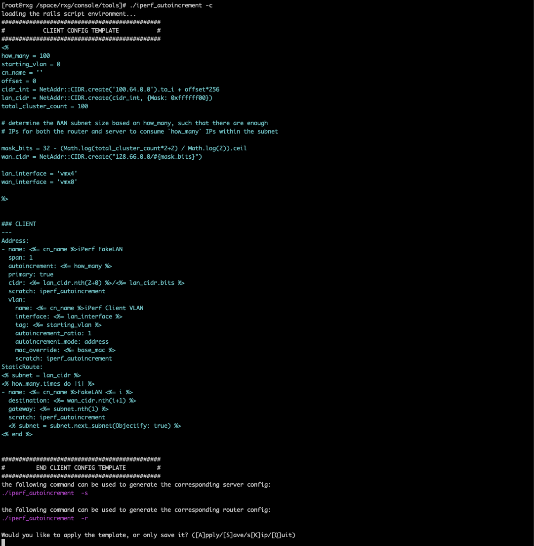
On the Client VM, we will run the following: ./iperf_autoincrement -c
-c sets the script to Client mode.
 Screen Shot 2024-01-29 at 3.46.07 PM.png 161.5 KB
Since this is the first time running the script we want to tell it to Save the template, hit S then enter. Once it is saved we want to exit the script, we need to adjust the template before continuing.
<% how_many = 100 starting_vlan = 100 cn_name = '' offset = 0 cidr_int = NetAddr::CIDR.create('100.64.0.0').to_i + offset*256 lan_cidr = NetAddr::CIDR.create(cidr_int, {Mask: 0xffffff00}) total_cluster_count = 100 base_mac = "00:00:00:00:00:00"
determine the WAN subnet size based on how_many, such that there are enough
IPs for both the router and server to consume how_many IPs within the subnet
mask_bits = 32 - (Math.log(total_cluster_count*2+2) / Math.log(2)).ceil wan_cidr = NetAddr::CIDR.create("128.66.0.0/#{mask_bits}")
lan_interface = 'vmx4' wan_interface = 'vmx1'
%>
how_many is how many iperf servers/clients we want to use. Here we will leave it at the default 100. starting_vlan is the VLAN we are going to start with, in this case VLAN 100 is the starting VLAN.
Adjust the lan and wan interfaces as needed. We should not need to adjust the other variables. Once the template is updated we can apply it to the Client system.
 Screen Shot 2024-01-29 at 3.50.57 PM.png 39.31 KB
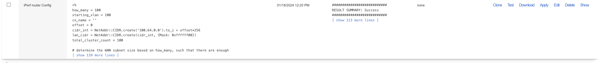
Next SSH into the Router machine, run the same command from the cli except this time it will be -r (for router) instead of -c. : ./iperf_autoincrement -r
Again we will want to save the template.
<% how_many = 100 starting_vlan = 100 cn_name = '' offset = 0 cidr_int = NetAddr::CIDR.create('100.64.0.0').to_i + offset*256 lan_cidr = NetAddr::CIDR.create(cidr_int, {Mask: 0xffffff00}) total_cluster_count = 100
determine the WAN subnet size based on how_many, such that there are enough
IPs for both the router and server to consume how_many IPs within the subnet
mask_bits = 32 - (Math.log(total_cluster_count*2+2) / Math.log(2)).ceil wan_cidr = NetAddr::CIDR.create("128.66.0.0/#{mask_bits}")
lan_interface = 'vmx3' wan_interface = 'vmx1'
%>
Adjust how_many and starting_vlan to the same values as the previous client (both 100 in this case). Adjust the lan and wan interface as needed.
Then apply the template.
 Screen Shot 2024-01-29 at 3.55.03 PM.png 47.1 KB
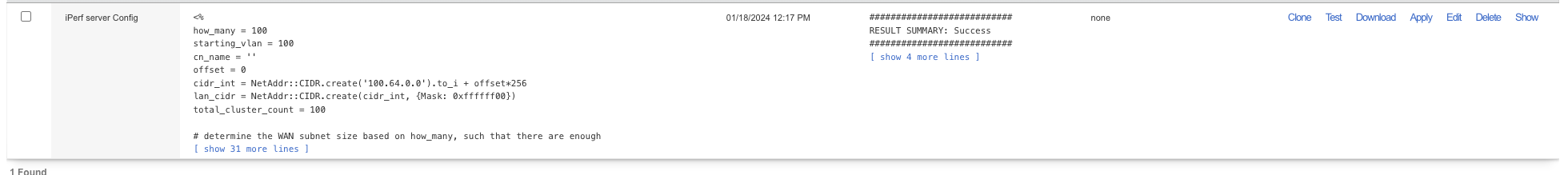
Lastly repeat the same steps on the Server VM.
SSH in and run: ./iperf_autoincrement -s
the -s flags it for the Server configuration.
<% how_many = 100 starting_vlan = 100 cn_name = '' offset = 0 cidr_int = NetAddr::CIDR.create('100.64.0.0').to_i + offset*256 lan_cidr = NetAddr::CIDR.create(cidr_int, {Mask: 0xffffff00}) total_cluster_count = 100
determine the WAN subnet size based on how_many, such that there are enough
IPs for both the router and server to consume how_many IPs within the subnet
mask_bits = 32 - (Math.log(total_cluster_count*2+2) / Math.log(2)).ceil wan_cidr = NetAddr::CIDR.create("128.66.0.0/#{mask_bits}")
lan_interface = 'vmx3' wan_interface = 'vmx1'
%>
Adjust the how_many and starting_vlan, again 100 for both in this example.
Adjust the lan and wan interface as needed. Apply the template.
 Screen Shot 2024-01-29 at 3.58.58 PM.png 47.76 KB
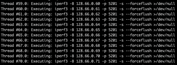
Now the Client, Router, and Server systems have the required config. Next ssh into the Server system, we will need to run the script again to kick off the iperf servers so that client system can connect to them. The command is below.
./iperf_autoincrement -s -n 100 -S -k
This will run the script again, -s sets the mode to server, -n 100 sets the number of testers to 100 (this value can't exceed the how_many value but can be less), -S is for nicer stats. Usually I will set -S on one system and leave it off on the other this will give us the raw values and the easier to read version. -k skips template generation (we only need to do this once).
Hit Y to proceed with testing mode.
This will start the ipef servers.
 Screen Shot 2024-01-29 at 4.08.39 PM.png 59.18 KB
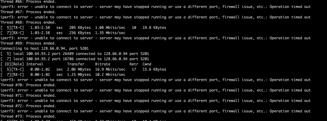
Now SSH into the Client machine, and run the following.
./iperf_autoincrement -c -n 100 -k
-c sets mode to client, -n 100 is how many testers (can't exceed the how_many value, but can be smaller) -k to skip the templates.
You may see some errors at this point
 Screen Shot 2024-01-29 at 4.11.20 PM.png 98.9 KB
This is because it needs to log in all the sessions, let it run but go into the Admin GUI of the Router system and navigate to Instruments::Device sessions. It needs to log all 100 testers in, once we see 100 login sessions (or the number you specified in the how_many) we can stop the process by hitting ctrl-c in the terminal window.
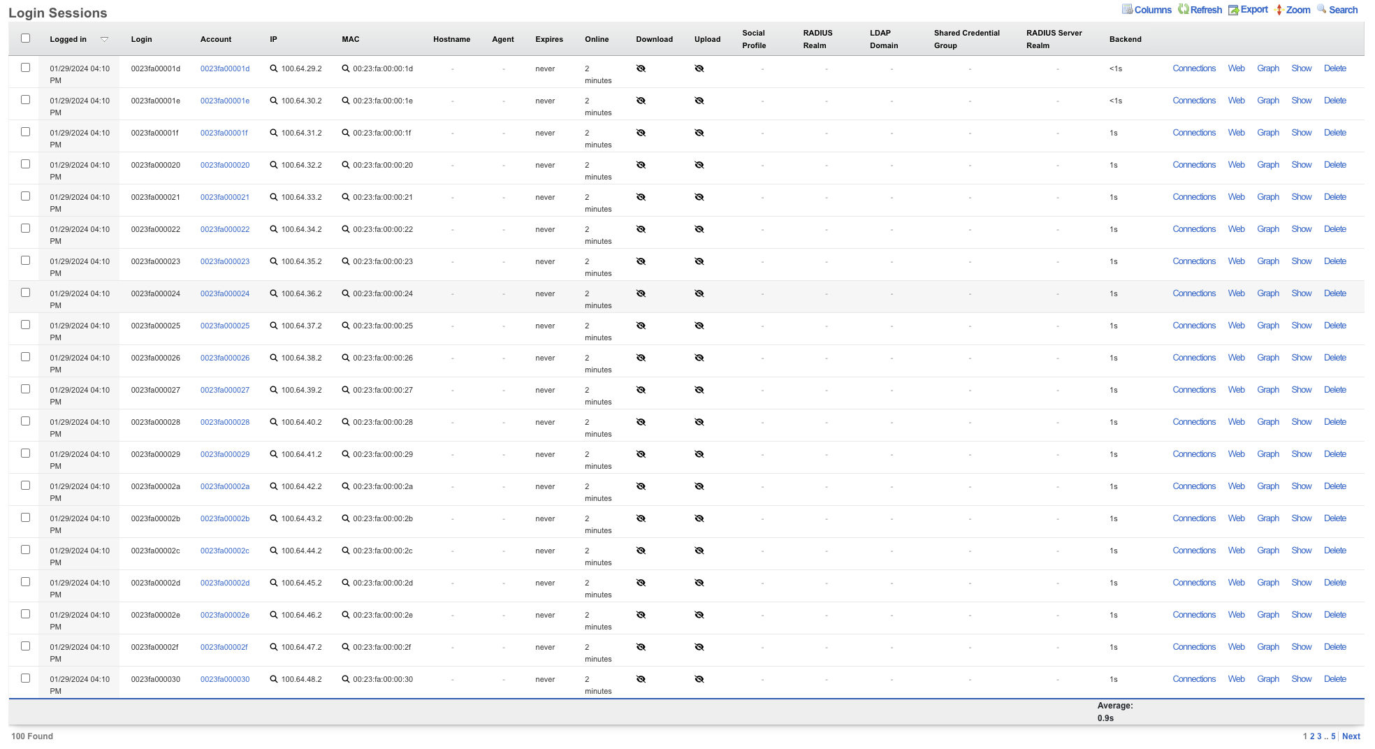 Screen Shot 2024-01-29 at 4.13.33 PM.png 304.17 KB
Now that all the devices are logged in we can start the test again by running the same command on the client system.
./iperf_autoincrement -c -n 100 -k
Now we have a test running. As you can see here we are only getting around 200Mbps in this setup.
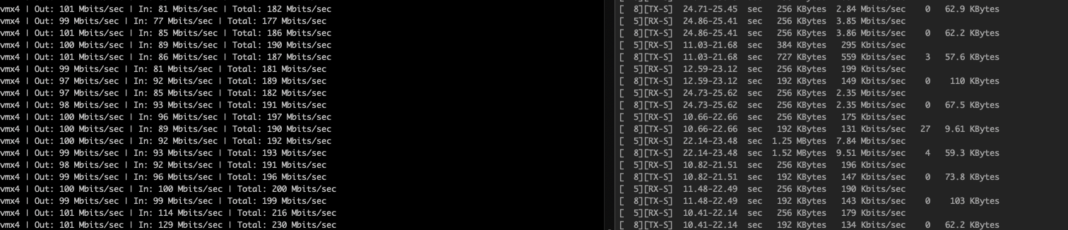 Screen Shot 2024-01-29 at 4.16.14 PM.png 154.67 KB
The reason for the slow speeds in this case was because my uplink on the client machine was only set to 100Mbps, adjusting this to 1Gbps I am now getting much higher speeds.
Screen Shot 2024-01-29 at 4.16.14 PM.png 154.67 KB
The reason for the slow speeds in this case was because my uplink on the client machine was only set to 100Mbps, adjusting this to 1Gbps I am now getting much higher speeds.
 Screen Shot 2024-01-29 at 4.21.15 PM.png 108.84 KB


