rXg LAN-side firewall configuration
January 27, 2025
Introduction
The rXg platform includes a fully functional firewall, permitting selective filtering of traffic between any reachable interfaces / devices. The configuration process is somewhat different compared to other dedicated firewall devices, and needs some explanation, as covered in this KB document.
Initial Setup
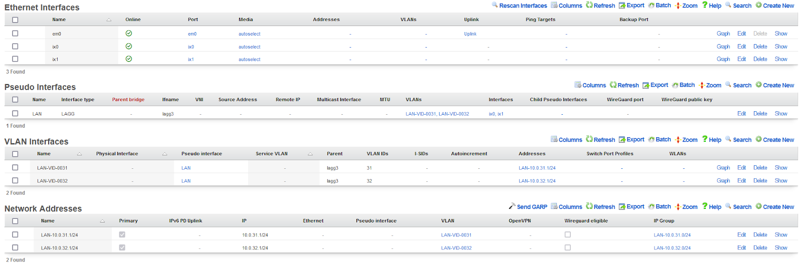
This example uses two LAN-side VLAN-tagged subinterfaces, i.e., LAN-VID-0031 (using VID 31) and LAN-VID-0032 (using VID 32), created on a LAGG interface named ‘LAN’. LAN-VID-0031 and LAN-VID-0032 have local /24 prefixes associated with them: 10.0.31.1/24 (called ‘LAN-10.0.31.1/24’), and 10.0.32.1/24 (called ‘LAN-10.0.32.1/24’), respectively. The rXg used as an example for the KB document is running code 15.812, i.e., the latest stable version available at the time of writing.
The resulting configuration in the ‘Network::LAN’ scaffold are shown below:
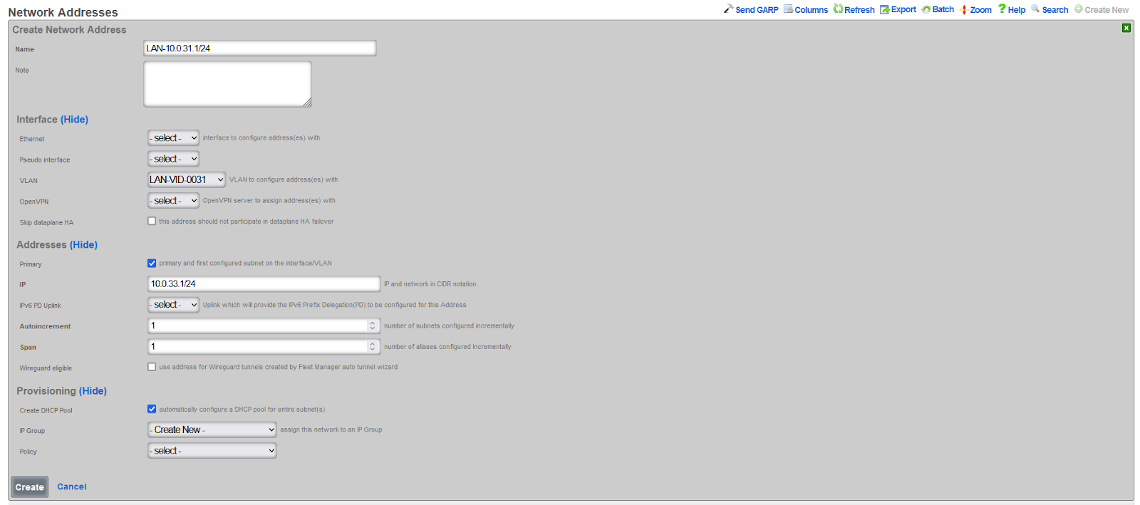
When creating new entries in the ‘Network Address’ scaffold, make sure that IP Groups are created, and the created prefix may be marked as primary. Select the ‘Create DHCP Pool’ option as well to automatically create a new DHCP pool associated with this prefix. It may be modified separately, if needed. The example below shows the configuration options for the ‘LAN-10.0.31.1/24’ Network Address entry. The ‘LAN-10.0.32.1/24’ Network Address entry is created in a very similar manner.
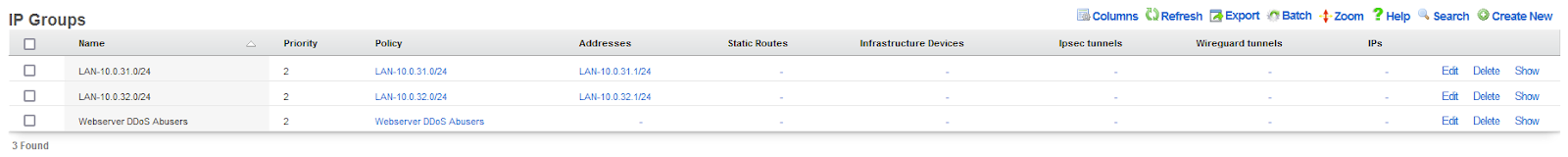
Names of both IP groups may be adjusted in the ‘Identities::Groups’ scaffold, as shown below:
The names and the scope of DHCP pools created for each VLAN subinterface can be adjusted in the ‘Services::DHCP’ scaffold, as shown below:
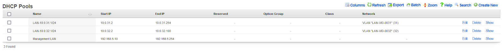
In the example shown above, the ‘’LAN-10.0.31.1/24’ pool was left in the default state, covering .2 through .254 addresses, while the ‘LAN-10.0.32.1/24’ pool was modified to cover .2 through .100 addresses, keeping the remaining ones unavailable for the DHCP-based allocation.
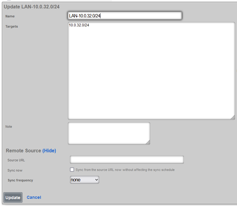
The next step involves creating WAN targets for individual prefixes, using the ‘Identities::Definitions::WAN Targets’ scaffold. WAN targets provide a very flexible mechanism to define different types of targets for firewall rules to act upon, including prefixes, hosts, etc., grouping them into logical entries. A single entry includes a list of destination IPs, CIDRs or Domain Names, one per line. Wildcard (*) character is supported in Domain Names. In this example, we intend to operate on complete prefixes, hence the entries will be limited to a single /24 prefix created previously. The example below shows the WAN target for 10.0.32.0/24 prefix. Note that it should be a network prefix, not a host prefix.
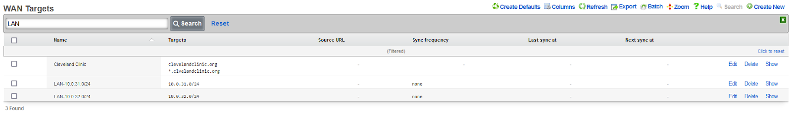
The resulting WAN Target entries for both LAN prefixes are shown below, demonstrating also the option of searching through the extensive list of pre-configured WAN Target entries.
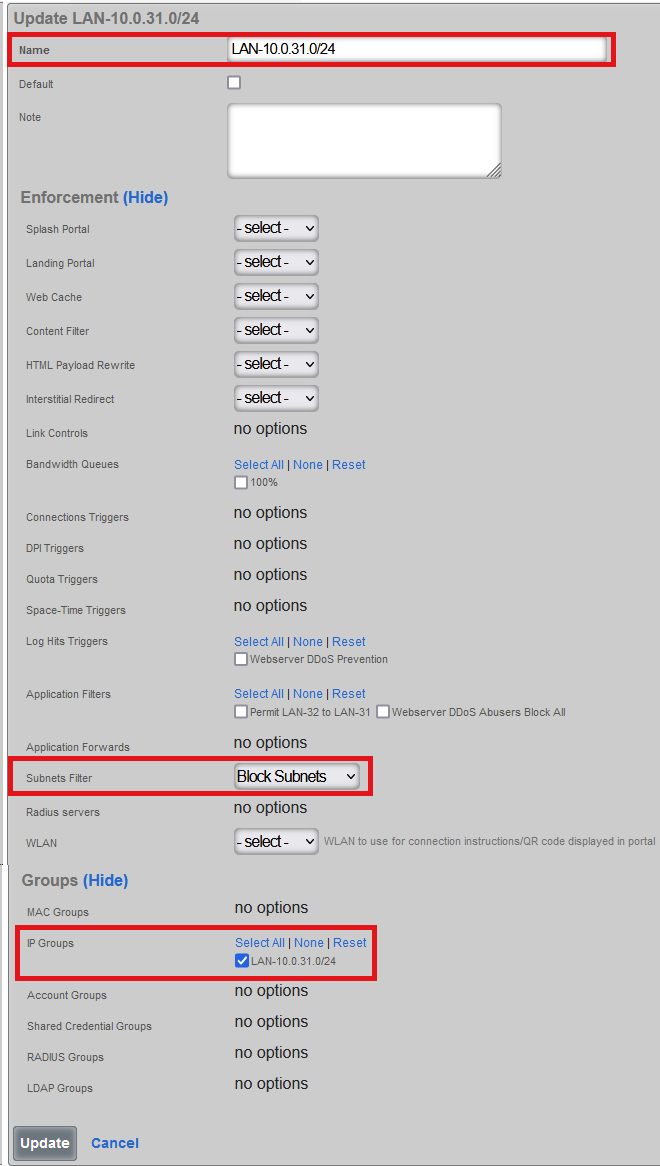
Next create specific policies for individual IP Groups, using the ‘Policies::Policies’ scaffold. By default, each IP Policy should be associated with the ‘Block subnets’ filter, to create a default deny filter behavior for individual prefixes. The resulting policy structure for the ‘LAN-10.0.31.0/.24’ entry is shown below, with the critical elements highlighted.
The last step features the creation of specific application definitions. A number of predefined applications can be readily found in the ‘Policies::Packet Filters::Applications’ scaffold. New SSH and TELNET applications are defined for this example, as shown below:
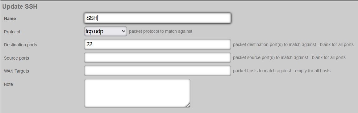
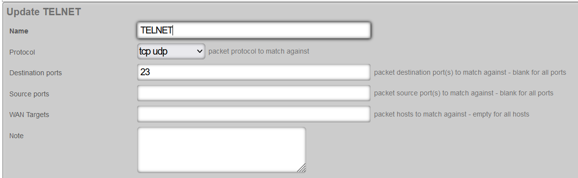
The example application definitions shown above are relatively simple and production definitions may become much more complex, including a list / range of source and destination ports, WAN target context, and different protocols. For the purposes of this example, SSH and Telnet services will be used.
Firewall configuration example
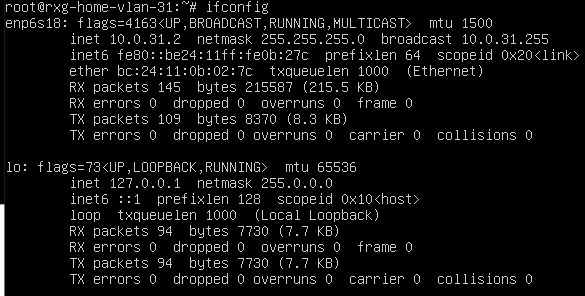
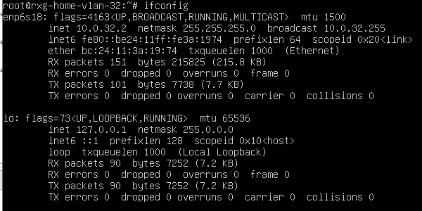
For the purposes of demonstrating the firewall functionality, two VMs will be used, one on each of the VLANs created before. DHCP-based address assignment is used. One VM is at 10.0.31.2 (VM-31) and the other one is at 10.0.32.2 (VM-32).
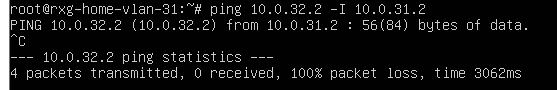
With the default ‘Block Subnets’ filter applied, the communication between both VMs is expected to be down, and any attempts to ICMP between them should fail, as shown below.
VM-31 to VM-32
VM-32 to VM-31

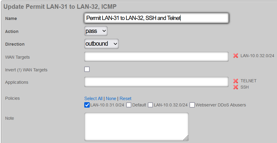
To create an exception and permit traffic from VM-32 to VM-31 (port 22 and 23 for SSH and Telnet services), a new firewall needs to be created using ‘Policies::Packet Filters::Application Filters’ scaffold as shown below:
- set ‘Action’ to ‘pass’, since it is an exception to the default deny rule implemented using the ‘Block Subnets’ filter
- set ‘Direction’ to ‘outbound’, since the rule permits outbound traffic from the 10.0.31.0/24 prefix to other targets
- select ‘LAN-10.0.32.0/24’ WAN Target entry created before to designate the target prefix for the traffic rule (destination)
- select ‘SSH’ and ‘TELNET’ from ‘Applications’ list, several entries may be selected at any time to build a broader rule
- select the ‘LAN-10.0.31.0/24’ Policy created before to designate the source prefix (via the associated Policy) for the traffic rule
Once the filters is created, ICMP between test VMs continues to fail, like before, with VM-32 unable to SSH / Telnet to VM-31

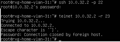
but with VM-31 able to SSH / Telnet to VM-32, as shown below:
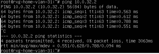
The communication between these two prefixes can be opened even wider, by removing the Application filter, in which case other services from VM-31 to VM-32 start working correctly.
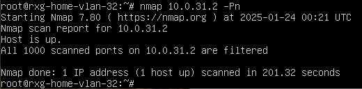
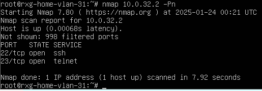
The proper filtering is further exhibited by running nmap on both VM instances, with the following results: VM-32 is unable to find any open ports on VM-31
while VM-31 is able to find open ports 22 and 23, which were explicitly permitted using the Application Filter rule shown above.
Firewall observations
Do note that the firewall rules are executed in order they are configured, from the top down, until the last match is made, providing a simple way of ordering individual firewall terms and controlling their order of execution. In the example below, when attempting to SSH or Telnet from 10.0.31.2 VM-31 to 10.0.32.2 VM-32, the last matching rule is the last one in the stack, hence it is executed.

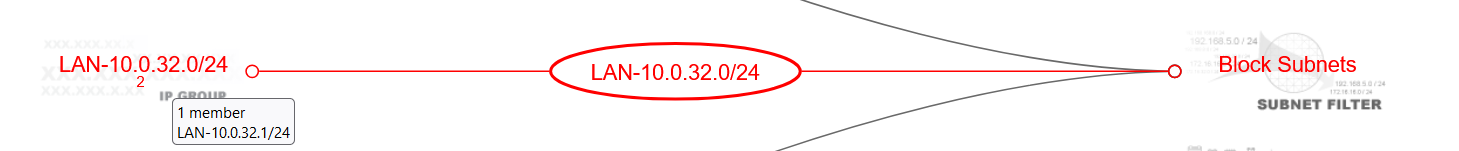
When attempting the same connectivity from VM-32 to VM-31, the default ‘Block Subnets’ filter rule is applied, displayed in a visual manner in the Policies scaffold, as shown below. The visual representation of relationships between individual IP Groups, Policies, and Filters / QoS / Triggers is a very powerful and convenient way to track behaviors applied to individual prefixes.

By hovering over the ‘LAN-10.0.32.0/24’ IP Group on the right, the following relationship is displayed, indicating that any communication from the 10.0.32.0/24 prefix to other prefixes (subnets) will be blocked, using the ‘Block Subnets’ filter.
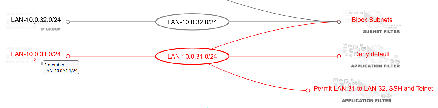
Conversely, the ‘LAN-10.0.31.0/24’ IP Group relationship, as shown below, shows three separate matches, whereby the order of applicability depends on the match and the structure of the given application filter. In case of a lack of applicable application filter, the default ‘Block Subnets’ filter is applied, preventing communication to other prefixes.
The combination of such subnet filters and application filters creates very flexible and powerful filtering capabilities, providing means to execute very tight control over communication between individual prefixes, applications, and hosts, depending on the IP Group, WAN Target, and Policy definitions.


